
Tech Tip: SVG Technique: Converting from Cartesian Coordinates
PRODUCT: 4D | VERSION: 12.2 | PLATFORM: Mac & Win
Published On: June 17, 2011
If you are transferring data from another system to SVG, you may have to deal with vector drawings that use "Cartesian" coordinates (the ones you learned about in high school algebra) to represent data. In the "Cartesian" coordinates system the (0,0) is at the lower left corner of the canvas, and the y-coordinates increase upward instead of downward, as in SVG.
Since the y-axis is "upside-down" relative to the SVG default the coordinates have to be recalculated. Rather than do it by hand, you can use a sequence of transformations to have SVG do all the work.
Consider the image below as described in some system that uses Cartesian coordinates -- note the greater y-axis values are at the top:
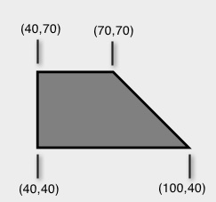
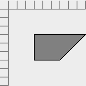
The next image is a typical direct translation from a non SVG source for the trapezoid shown above. The problem is that the long top-edge should be the bottom edge. The axes and offset have been included for reference and clarity.
To finish the conversion, the following steps were preformed:
For a more in depth description of what actually was done by the SVG engine, see Technical Note SVG Coordinate System
Since the y-axis is "upside-down" relative to the SVG default the coordinates have to be recalculated. Rather than do it by hand, you can use a sequence of transformations to have SVG do all the work.
Consider the image below as described in some system that uses Cartesian coordinates -- note the greater y-axis values are at the top:
The next image is a typical direct translation from a non SVG source for the trapezoid shown above. The problem is that the long top-edge should be the bottom edge. The axes and offset have been included for reference and clarity.
| $X_L:=0 $Y_L:=0 $SVG_T:=SVG_New SVG_SET_DIMENSIONS ($SVG_T;400;400;"mm") SVG_SET_VIEWBOX ($SVG_T;0;0;400;400) SVG_New_line ($SVG_T;$X_L+10;$Y_L+10;$X_L+100;$Y_L+10;"gray";1) SVG_New_line ($SVG_T;$X_L+10;$Y_L+10;$X_L+10;$Y_L+100;"gray";1) For ($Ndx;1;10) SVG_New_line ($SVG_T;$X_L;$Y_L+($Ndx*10);$X_L+10;$Y_L+($Ndx*10);"gray";1) SVG_New_line($SVG_T;$X_L+($Ndx*10);$Y_L;$X_L+($Ndx*10);$Y_L+10;"gray";1) End for SVG_New_polygon ($SVG_T;"40,40 100,40, 70,70 40,70";"black";"gray";1) |
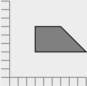
To finish the conversion, the following steps were preformed:
- Find the max y-coordinates in the original drawing. In this case it is 100, the endpoint of the y-axis in the original.
- Enclose the entire drawing in an SVG Group.
- Enter a translate that moves the coordinate system downwards by the max y value.
- The next transform is to scale the y-axis by a factor of -1, flipping it upside-down.
| $X_L:=0 $Y_L:=0 $SVG_T:=SVG_New SVG_SET_DIMENSIONS ($SVG_T;400;400;"mm") SVG_SET_VIEWBOX ($SVG_T;-1;-1;400;400) $SVG_Grp_T:=SVG_New_group ($SVG_T;"MyGroup") SVG_New_line ($SVG_Grp_T;$X_L+10;$Y_L+10;$X_L+100;$Y_L+10;"gray";1) SVG_New_line ($SVG_Grp_T;$X_L+10;$Y_L+10;$X_L+10;$Y_L+100;"gray";1) For ($Ndx;1;10) SVG_New_line ($SVG_Grp_T;$X_L;$Y_L+($Ndx*10);$X_L+10;$Y_L+($Ndx*10);"gray";1) SVG_New_line ($SVG_Grp_T;$X_L+($Ndx*10);$Y_L;$X_L+($Ndx*10);$Y_L+10;"gray";1) End for $Use_T:=SVG_New_polygon ($SVG_Grp_T;"40,40 100,40, 70,70 40,70";"black";"gray";1) SVG_SET_TRANSFORM_TRANSLATE ($SVG_Grp_T;0;100) SVG_SET_TRANSFORM_FLIP ($SVG_Grp_T;True) |
For a more in depth description of what actually was done by the SVG engine, see Technical Note SVG Coordinate System